17th World Conference on Nondestructive Testing, 25-28 Oct 2008, Shanghai,
China
Aerospace NDT with Advanced Laser Shearography
John W. NEWMAN
Laser Technology Inc.
Abstract:
Shearography nondestructive testing has evolved considerably since first used on
a
production aircraft program in the USA in 1986. Shearography laser
interferometric imaging
methods measure test structure deformation due to an applied engineered change
in stress. The
resulting changes in Z-Axis strain component reveal images of subsurface defects
such as
disbonds, delaminations, core defects and impact damage in aerospace structures.
Shearography
NDT provides high thru-put, cost-effective productivity enhancements, improved
manufacturing
processes and quality. Development of digital CCD cameras, the PC and small,
high power
solid-state lasers have led to dramatic performance improvements in shearography
instruments
and systems. Shearography is currently in use on a wide variety of aircraft
including F-22, F-35
JSF, Airbus, Cessna Citation X, Raytheon Premier I and the NASA Space Shuttle.
This
presentation will provide a brief background on shearography NDT technology as
well as recent
developments in production and portable on-aircraft shearography inspection
technologies and
applications.
Key Words: Aerospace NDT, shearography NDT, honeycomb structure, NDT, disbond,
damage, delamination
1.0 Background
In today’s highly competitive aerospace environment, a capable high-speed
inspection
technology is critical. Shearography nondestructive testing is providing a
better and faster means
to nondestructively inspecting new aircraft both during manufacturing and in the
field.
In the quest to maximize fuel economy and performance, engineers have turned
from riveted
and bonded aluminum structures to solid composite laminates, composite sandwich
panels with
honeycomb or foam cores and tape wound composite structures such as fuselages.
The
traditional methods for nondestructive testing, such as ultrasonic (UT) C-Scan,
may not provide
the best defect detection capability for these new materials and geometries and
are slow with a
typical through-put of just 10 sq. ft./hour. Further, the process of
manufacturing complex
composite structures requires a means for fast inspection to provide a process
control feedback
and to ensure quality and reliability at the lowest possible cost. In many
aerospace programs
today, laser shearography is providing a large part of the solution.
2
2.0 History of Shearography NDT
The electronic laser shearography imaging interferometer was pioneered in the
early 1980’s
by three researchers, Dr. John Butters at Loughborough University in the UK, Dr.
S. Nakadate in
Japan and Dr. Mike Hung at Oakland University in the USA. The author’s team at
Laser
Technology Inc. led the development of the shearography camera as a tool for
nondestructive
testing, delivering the world’s first production shearography NDT system to
Northrop Grumman
in 1987 for the manufacturing of the USAF B2 Stealth Bomber.
In the last twenty years more than 1,200 shearography systems have been
integrated into the
manufacturing process for aircraft composites, tires and high-reliability
electronics. As with all
NDT methods and technologies, shearography’s strengths and weakness must be
completely
understood, and applications qualified through Probability of detection (PoD)
verification with
written procedures and rigorous training for operators and engineers alike. Once
qualified,
however, shearography systems can operate with extraordinary efficiency reaching
through-puts
from 25 to 1200 sq. ft per hour, 2.5 to 120 times the typical 10 sq. ft./hour
inspection rate for
ultrasonic C-Scan.
Photo 2
This executive jet flap is
manufactured with GRP skins and
multiple foam cores with internal
bond lines making this part
extremely difficult to inspect using
traditional NDT technologies.
Photo 1
The USAF B-2 stealth
bomber was the first
aircraft to incorporate
Shearography NDT
technology in the
manufacturing of
complex composite
structures.
3. Shearography NDT
Unlike UT C-Scan, which uses a single transducer that requires a raster scan
over the part to
build up an image, Shearography is a whole field, real-time imaging technique
that reveals outof-
plane deformation derivatives in response to and applied stress. Using a slight
pressure
reduction in a shearography test chamber, critical defects are imaged and
measured in seconds.
The shearography camera detects surface bumps as small as 3 nanometers caused by
local strain
changes around subsurface defects as the pressure is reduced on the part. Vacuum
shearography
is highly effective for image disbonds, delaminations, core damage and core
splice-joint
separations. Other Shearography NDT techniques that are frequently used include
thermal pulse
shearography for non-visible impact damage, pressure shearography for damage to
composite
wrapped pressure vessels. Vibration shearography has been highly developed in
the last several
years by the author to inspect the foam on the external tank of NASA’s Space
Shuttle.
o
Photo 3
Shearography images above show disbonds in the flap, between the foam core and
GRP skins, on the left as the white/black indications in the unwrapped image or,
on
the right, as areas with fringe concentrations in the wrapped phase map. Time to
perform a shearography test of this 1.5 sq. ft. section of the flap is 4
seconds, 135
times faster than testing with UT C-Scan, if the test could be accomplished at
all
given the complex shape.
Photo 4
A typical digital shearography camera,
the LTI-5100, includes a built in laser, the
shearing image interferometer and image
processing computer. The aircraft radome
may be tested with thermal stressed by
applying a slight temperature change on the
order of 3-10°C.
(pdf)
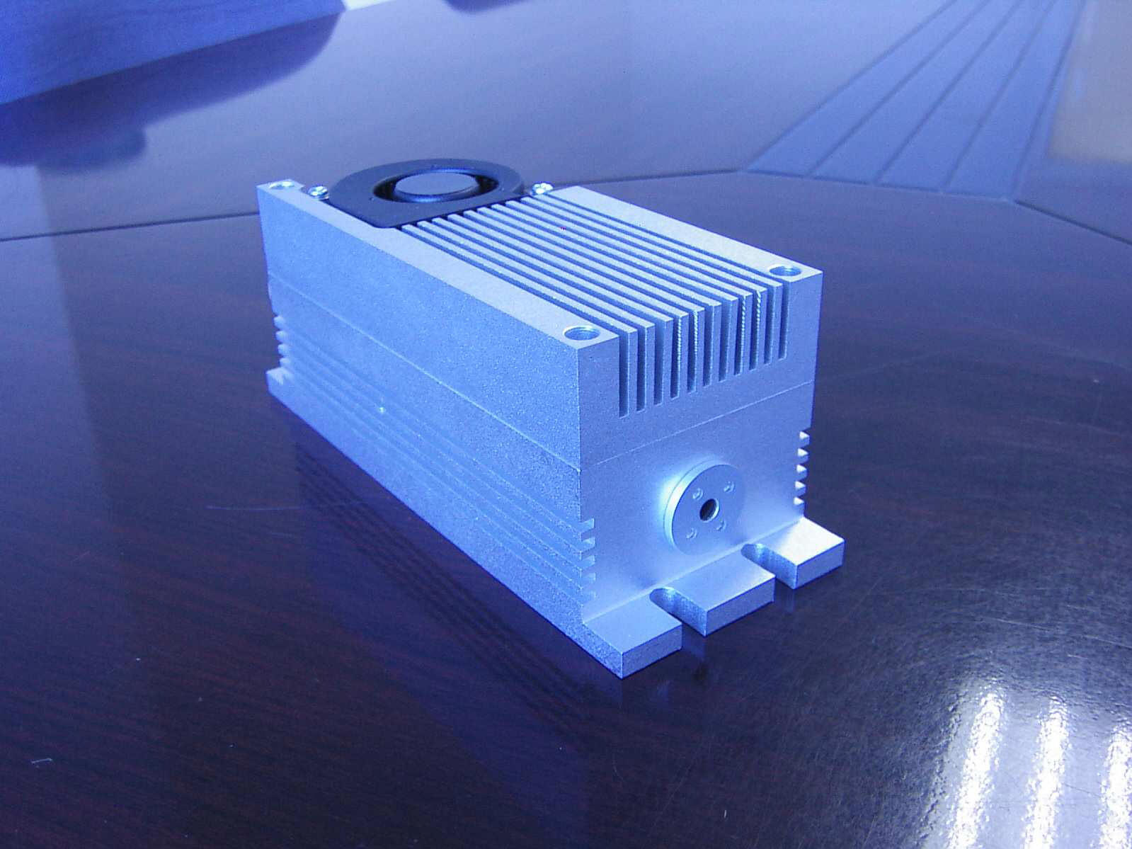
DPSS lasers for Aerospace NDT with Advanced Laser Shearography
DPSS 532 nm 1W laser DMPV-532-1 (532nm Diode Pumped Solid State Green Laser 1000mW)
| Model: DPSS DMPV-532-1 -
request a
quote -
buy from online store Wavelength (nm) 532 Output Power (mW) 1000 Working Mode CW Beam Mode Transverse TEM00 Longitude Multi-longitude Spectral Linewidth (nm) <0.1 Polarization Line polarization Polarization Ratio >100:1 Beam Quality (M2 factor) <1.2 Beam Divergence (full angle, mrad) 1.2~2.0 Beam Diameter at Aperture (mm) 1.2~2.0 Beam Roundness >90% Power Stability (RMS, over 8 hours) <5% Aperture Position (mm) 20 Laser Head Dimensions (L×W×H, mm) 180 x 62 x 62.5 External Modulation 5V TTL/5V Analogue Modulating Repetition 30KHz TTL/10KHz Analogue Cooling System TEC Warm-up Time (minutes) <15 Operation Temperature (℃) 18~30 Expected Lifetime (hours) >10000 Warranty Time 1 year |
|
DPSS 532 nm 3W laser DMPV-532-3 (532nm Diode Pumped Solid State Green Laser 3000mW)
![]()
Del Mar Photonics, Inc.
4119 Twilight Ridge
San Diego, CA 92130
tel: (858) 876-3133
fax: (858) 630-2376
Skype: delmarphotonics
sales@dmphotonics.com