Del Mar Photonics
Rutile (TiO2) prisms and their applications -
buy online - download brochure
Example of application:
High dispersion rutile prism for tuning dye lasers
Review of Scientific Instruments -- October 1976 -- Volume 47, Issue 10, pp.
1293-1295
J. Krasiski and W. Majewski
Institute of Experimental Physics, University of Warsaw, Hza 69, 00-681 Warsaw,
Poland
A high dispersion rutile prism was constructed to tune dye lasers. With the help
of this prism, a laser line was produced with smaller spectral width and greater
strength than that obtained with the use of a 1800 grooves/mm diffraction
grating. This prism is as durable as a glass prism.
Del Mar Photonics offers optical elements made of high quality synthetically
grown Rutile Titanium Dioxide crystals. Rutile’s strong birefringency, wide
transmission range and good mechanical properties make it suitable for
fabrication of polarizing cubes, prisms and optical isolators. Boules having
high optical transmission and homogeneity are grown by proprietary method.
Typical boules have 10 - 15 mm in dia. and up to 25 mm length. Optical elements
sizes - from 2 x 2 x 1 mm to 12.7 x 12.7 x 12.7 mm. Laser grade polish quality
is available for finished elements. So far we the largest elements that we
manufactured are
12 x15 x 5 mm, in which optical axis is parallel to 15 mm edge, 5 mm is
along
beam path, 12 x 15 mm faces polished 20/10 S/D, one wave flatness,
parallelism < 3 arc.min. (better specs. available on request).
| Standard Specifications (buy
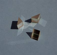
online): Rutile (TiO2) coupling prism
Material: single crystal TiO2
Sizes: 5x5x5 mm +/- 0.2 mm
Angles:45-45-90 deg.+/-10 arcmin
Polish quality: 20/10Scratch/Dig
Surface flatness: lambda @ 633nm
Parallelism: <5arcmins
Orientation: Z-axis along prism thickness +/- 15 arcmin
|
 |
|
|
 |
|
|
Research description for a Rutile coupling prism
This description will give a brief insight into our research at the
Light Technology Institute of the University of Karlsruhe (TH), Germany. One of
our research fields is the development of electrically pumped organic
semiconductor thin film lasers. Due to the complex behavior of these lasers
numerous electrical and optical characterization is necessary. One of the most
important optical properties of these organic semiconductor laser structures is
the attenuation coefficient of the multilayer waveguide, which has to be
carefully optimized to reduce waveguide losses 1. The first step in the
optimization process is the numerical simulation of the anticipated waveguide
design. Next, the optimized sample structure is fabricated and characterized in
our attenuation measurement setup. This measurement is done as follows:
A Rutile coupling prism is pressed onto the waveguide. A laser beam is then
coupled into the prism so that total reflection occurs inside the prism at the
interface to the waveguide. In the vicinity of the waveguide the overlapping
incident and reflected beam generate a standing wave. The evanescent field of
that standing wave penetrates into the waveguide.
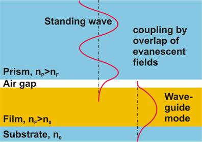
Evanescent field coupling
Under a certain angle and if the phase match conditions are fulfilled, the
evanescent field stimulates a mode that is guided by the waveguide. The phase
match condition can only be achieved when the refractive index of the prism is
at least as high as the effective refractive index of the waveguide. Owing to
its high refractive index, Rutile is an ideal material for use as a coupling
prism in such a prism-coupler waveguide attenuation measurement setup.

Beam coupling into waveguide
A small fraction of the guided light is scattered out of the waveguide. The
intensity of this scattered light is assumed to be proportional to the intensity
of the guided light. Thus the intensity distribution inside the waveguide along
the propagation direction can be directly determined through measuring the
intensity of the scattered light.
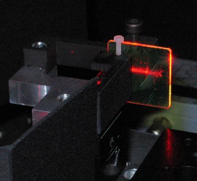
Streak caused by scattering inside the waveguide
The intensity distribution is detected with a computer controlled, cooled CCD-Camera.
Finally the attenuation coefficient is extracted from the measured data.
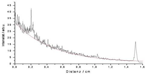
Intensity distribution measured with CCD-Camera
The following two figures show the setup that was used for the measurements.
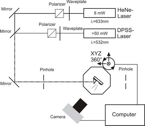
Schematic of the Setup
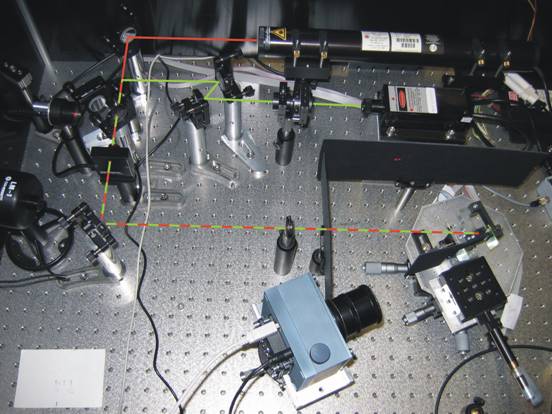
Photography of the Setup
Additionally, it is possible with our setup to measure the refractive index and
the thickness of waveguides that support a minimum of two guided modes. These
parameters can be extracted from the dependency between coupling angle and
effective refractive index.
Keywords: Prism, Coupling, Thin film waveguide, Waveguide losses, scattering,
Effective refractive index, Organic semiconductor lasers, Polymer, Small
molecule, Evanescent field, CCD-Camera, Coupling angle
1 M. Reufer, J. Feldmann, P. Rudati, A. Ruhl, D. Müller, K. Meerholz, C.
Karnutsch, M. Gerken, and U. Lemmer, Appl. Phys. Lett. 86, 221102 (2005).
 |
MSc.Christian Karnutsch
Lichttechnisches Institut
Universität Karlsruhe (TH)
Geb. 30.34
Kaiserstraße 12
D-76131 Karlsruhe
Raum: 126
Telefon: +49 721 608 7742
Telefax: +49 (0)721 608 - 2590 |
Del Mar Photonics


