Q: What
is the difference between your two phosphor screen mcp's. I see that one has a
glass plate and the other has a fiber plate, but is there an advantage to one
over the other?
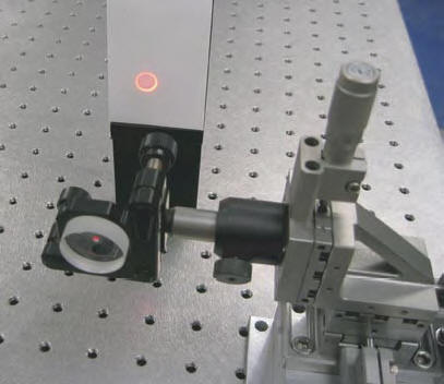
A: It
depends on image readout method. In case of phosphor screen on a glass plate
(GPS model) image is registered with a CCD camera or visually (for example, in
case of beam alignment application). When using phosphor screen on the fiber
plate (IFP model) it can be transferred directly to CCD using fiber tape without
additional optics.
Q: Ultimately,
I would like to have a MCP with phosphor output to look at electron spatial
distributions, but I will also need access to the time resolved signal. Can I
pull the time resolved signal off of the phosphor screen just as if it were a
metal anode? If so, are there any cautions, recommended ways of doing this, and
what time resolution can I expect?
A: Phosphor
screen is coated with a thin metal layer (typically Al), which is important in
order to avoid charge effects and obtain uniform electric field between MCP-Out
and phosphor. This metal layer act as a regular metal anode and provide a time
resolved signal. Luminescent signal directly from the phosphor screen can also
provide time-resolved signal, which is limited by the phosphor respond time. We
offer P47 phosphor that have decay time about 80ns, which is much shorter that
decay time for the most popular phosphor P20. New, faster phosphors are under
development.
Q: How
do you recommend making connections to your mcp's? The spot welder I have access
to is rather large. How big are the connection tabs, they look quite small in
the pictures? What material are they?
A: MCP
housing metal is KOVAR. It’s chosen because it had thermal expansion coefficient
close to glass and ceramics. Our assemblies usually supplied with stainless
still wires spot-welded to the tabs.
Q: Could
you tell the advantage of having a fibre optic plate against a phosphor screen,
and how does one obtain an image from the plate? Can you use a fibre optic
bundle to relay the image to another flange?
A: Image
is registered with a CCD camera or visually (for example, in case of beam
alignment application). When using phosphor screen on the fiber plate (IFP
model) it can be transferred to CCD using fiber taper or relayed to another
flange using optic bundle.
Q: (question
received from reseller) This customer has received this detector, but it's not
clear to know how to connect/supply the electrical operation condition. This
customer thinks it should be 4 electrical connector, but there is 3 connector.
A: The
reason we have 3 connectors (instead of 4) is the fact that we use "matched" MCP
pair. That means MCPs have the same resistance and are in direct contact with
each other. Matched pair needs only one voltage to be applied between MCP-In of
the first MCP and MCP-Out of the second MCP. In the attached file "MCP wiring"
we show one example of MCP detector wiring. Please note that only voltage
difference between MCP-In, MCP-Out and Anode is important for detector
operation. An absolute values of all this voltages depends on your customer
set-up, type of particles to be registered (electrons, ions, photons etc.). For
example MCP-In may be positive, negative or zero (ground). U (MCP-Out) = U
(MCP-In) +2000V, U (Anode) = U (MCP-In) + 2200V. The values of impedance and
capacitor depend on customer registration electronics. Typical values are 50Ohm
and 1000pF.
Q: During
unpacking, are there some warning procedures?
A: Detector
should be opened carefully and placed in the vacuum chamber as soon as
possible.
Q: From
your mail I understood the following: you can purchase the MCP-GPS34 assembly
complete but demounted. We are interested in that solution but I like to be
sure not to receive just the two MCP's and the phosphor screen. I know very well
that critical points are the correct distance between MCP's and from screen and
MCP for that reason I like to buy a tested assembly like yours.
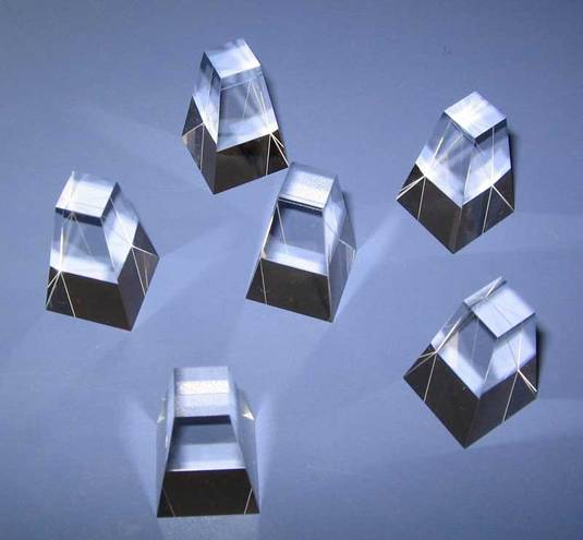
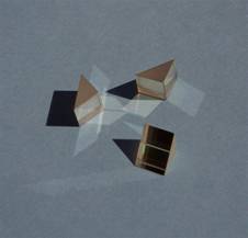
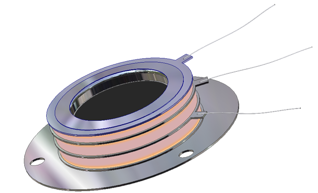
A: An
assembly consists of two main elements: MCP holder and luminescent screen. You
can see 3D images of both parts in attached files. These two elements are fitted
to each other in a way to provide optimum distance between Phosphor screen
surface and MCP-out surface. This distance can also be further adjusted (if
required) by placing a foil ring (30-100micron thick) on MCP holder before
placing MCP. These assembly is designed and tested to obtain maximum spatial
resolution in night-vision applications - and of course it will also work with
maximum spatial resolution in other applications.
Q: Concerning
the spatial resolution the value you quoted it is comprehensive >of the phosphor
response ? Which kind of phosphor it is used (P11, P20 ...)?
A: Standard
phosphor used is P20. Any other can be applied at customer request. Spatial
resolution is limited not by the phosphor type, but the phosphor particles size.
If particles are small enough, then the limiting factor is MCP channel size and
pitch as well as distance/voltage between MCP and phosphor screen.
Q: We
did not use the flange mounted detector received from you yet. The reason was we
did not have experiments in ultra-high-vacuum, just in vacuum of 10e-7 torr.
A: Of
course it will work at this vacuum too. If you do not use it, please try to keep
it in vacuum or in a dry atmosphere since the MCP glass react with a moisture.
Q: The
detector worked pretty good with clusters but due to some voltage jumping (over
3kV) from power supply we lost the MCPs.
A: You
should use a current limiting resistor to avoid serious damage to MCPs in case
of discharge.
Q: I
need you to confirm that we can also use the mcp for positive ion detection,
i.e. have a large negative voltage on the front plate while the back side is on
-50 to -200V and the anode on ground.
A: Yes,
you can do that. However, maximum voltage difference applied between MCP-In and
MCP-Out for 2 MCP assembly should not exceed 2200V (1100V per plate). For small
ions 2keV is enough energy for efficient electron emission from MCP surface.
However, if you plan to detect heavy ions, for example biomolecules, you need
additional acceleration voltage. As you probably know most of MALDI-TOF systems
accelerate ions to 20keV and higher.
Q: It
is not clear to me if I have to directly supply the voltage to the anode, i.e.
if I have to connect the fin of the anode to a power-supply, and extract the
output signal from a T-wiring connection?
A: When
applying high voltages to MCP detector electrodes including anode care should be
taken to avoid unwanted discharges that can destroy MCPs. Discharges can develop
in low vacuum conditions as well as in high vacuum along detector isolating
surfaces if they are not clean enough or due to deposition of different
materials from ion sources, pumps etc. The main approach to protect detector is
to place safety resistors that will limit maximum average current in
corresponding circuits. Typical resistance value of 100Kohm will limit maximum
average current to 20mA at high voltages around 2kV. Signal connector should be
wired to anode through a High Voltage rated (3kV) capacitor. Typical capacitance
is about 1000pF.
Q: Incidentally
I am confused by you web description that seems to imply that a time resolution
of less than 1ns can be obtained using a simple planar metal anode. I thought
one had to be careful to match the anode to the (50 Ohm) output signal cable,
usually using some sort of matching cone? and Is it necessary to make an
impedance adaptation of the anode? I am extracting the signals with an
UHV-compatible 50Ohm coaxial cable and sending them to an amplifier and to a
discriminator (pulse-mode operation).
A: For
typical anode capacitance of 4pF and R=50 Ohm RC=200ps. If you are looking for
time resolution in subnanosecond (0.2ns) range you should think about impedance
matching (adaptation) of the anode. Creating specially shaped anodes usually
does it. In most applications time resolution is limited by registration
electronics and is in 1-10ns range. In this applications signal is integrated by
electronics with a typical time constant much larger than RC.
Q: I
read that the resistance of each MCP in my assembly is 2.0*10^8 Ohm. Does this
mean that the overall resistance MCPin-MCPout in chevron assembly is
4.0*10^8Ohm?
A: Yes,
an overall resistance R of the MCP assembly in chevron configuration is a sum
(R1+R2) of MCP-In resistance R1 and MCP-Out resistance (R2).
Q: What
is the value of the MCP-Anode capacity?
A: The
capacitance is affected by three factors: the area of the plates, the distance
between the plates, the dielectric constant of the material between the plates.
We can estimate anode capacitance in two different ways: as single metal
electrode or as a capacitor with two parallel plates (anode and MCP surface).
For a single metal electrode in vacuum an estimated capacitance C is equal
C=D/(9*10^11) F=1.1*D pF, where D is the size of the electrode in cm. For
electrode size D=3.5cm C is about 4pF. The capacitance of a capacitor with two
parallel plates in vacuum can be estimated using the formula: C = 9A/d, where C
is capacitance in pF (picofarads), A is the area of one plate in m2, and d is
the distance between plates in m. This estimation also gives a value about 4pF.
Q: I
read that the MCP-in is supposed to be operated at ground voltage. Is it
possible to apply it a slightly positive voltage, let's say +50 Volts, to induce
electrons to hit the MCP?
A: In
general, MCP assemblies can be operated with any electrode (MCP-in, MCP-out or
anode) at a ground potential. When detecting electrons it's also possible to
apply positive voltage to MCP-In electrode, keeping voltages between MCP-In
MCP-Out and MCP-Out and Anode as recommended:
Between MCP-in and MCP-out: Set this voltage according to the required gain, 700
-1000V per MCP typical, 1100 V maximum, MCP out at positive polarity.
Between MCP-out and single anode: This is normally set at about 100 - 200 V.On
the other hand, one should take into account the following: Positive potential
on the MCP-In electrode can result in higher noise signal from residual
electrons in the vacuum chamber. Background electrons can be generated by ion
pumps, external laser and UV sources, electrical discharge near high voltage
electrodes etc. Adding small positive voltage (around +50V) may be not enough
for efficient detection of electrons. It was experimentally shown that for
better detection efficiency incoming electrons should be accelerated to about
700V.
Q: I
read that the voltage MCPout-Anode is +200 Volts. Do you mean that when the
MCPout is biased to +2000 Volts, the voltage induce on the anode is typically
+200 Volts?
A: Recommended
voltages are as follows: MCP-In = 0 (ground), MCP-Out = +2000V, Anode = +2200V
For efficient detection of incoming electrons the following voltages can be
used: MCP-In = +700V, MCP-Out = +2700V, Anode = +2900V
Q: Which
kind of connection is set on the output anode to collect the signal? BNC, SMA,
SHV coaxial?
A: Detector
electrodes including anode have fins that can be connected to any standard
connector.
Q: Can
the whole stuff be baked? Can be operated in UHV (10^-10 Torr) without
contaminating vacuum?
A: Whole
MCP assembly can be baked up to 350°C. It's UHV compatible.
Q: Does
MCP detector present insulator parts in the front, which can be charged by
electron impacts?
A: No.
Q: Does
the detector ship as an assembly?
A: We
ship detector as assembly. We also can ship detector premounted on standard
vacuum flanges.
Q: Do
you have a typically wiring diagram for detecting positive and negative ions in
a ToF? What external resistors and capacitors are recommended?
A: Typical
wiring is described in the brochure. When MCP input is at a ground potential,
typical wiring diagram is the same for detection positive or negative ions in
ToF systems. External resistors and capacitors should match input parameters of
preamplifier. Most commonly used are 50 Ohm and 1000 pF (rated up to 3kV).
Q: You
don't have an electrode between the MCPs, which means that you do not ensure
that you have the same potential drop over both MCPs. Is the resistance of the
MCP plates so well defined that this is not a problem?
A: You
are right, there is no separate electrode between MCPs in our standard
assemblies. We use matched MCPs. Matched means that they have same resistance
within 10% (we choose usually even less difference). We also make sure that the
nominal operation voltage of two MCPs is about the same.
Q: We
were thinking to remove the 3 fins that are supposed to be used for biasing the
MCP and substitute them with some connectors we made. In order to attach these
new connectors we were thinking to spot-weld them to the little metallic parts
where the bias fins are actually connected. Anyway, this metallic part are
directly connected to the MCP, so they get an electric discharge when I make the
spot-weld. My question is if the spot-welding operation can somehow damage the
MCP.
A: When
making a spot-welding, place fins directly on the ground electrode (copper
plate). In this case the current will go directly through this part without
circulating around electrode. That will minimize any effects of welding current
on MCP. It’s also necessary to protect MCP surface from any hot particles
generated by sparks. Just place any protective screen between welding sport and
MCP to prevent direct exposure of the MCP to any possible discharge erosion
products.
Q: I
am confused by your web description which says the MCP has diameter 24.2 or
24.8mm, thickness 0.46mm, and effective area 18mm. Presumable you mean effective
diameter. Is it that the clamping ring is about 3.5mm wide, or have you allowed
for other losses at the edge?
A: In
fact actual effective diameter is larger than 18mm, but MCPs with diameter of
24.8mm are traditionally rated by MCP manufacturers as 18mm active diameter
plates.
Q: I
have looked through your web page but I was unable to spot a microchannel plate
assembly associated with a metal anode that was matched to, say, a 50 Ohm
transmission line. I am interested in an overall timing resolution of <100
picoseconds; 50 ps would be better. I am not interested in a position sensitive
readout.
A: We
do not offer assemblies with 50-100ps resolution at this time.
Q: I
noticed that the bias angle is different from the plates we are using now. What
are the consequences of this difference? I would guess that this would result in
a loss in gain. (We use two plates in a Chevron configuration.)
A: As
you probably know, the main application of MCPs is in the night vision devices.
In this application typical currents are much higher than in ion-detection
applications. Large bias angle (about 12-13 grad) is used to avoid an effect of
ion feedback on photocathode. Ion feedback is a flow of ions spattered by
electron avalanche from MCP channel wall, in the direction opposite to electron
avalanche, towards MCP entrance and then onto photocathode surface. Ion feedback
is negligible in ion detection applications and has no any serious effect, as
there is no photocathode at all. In general, gain depends on the bias angle, but
usually this dependence is not important and can be easily compensated by
applied voltage. In fact gain variation in different MCP manufacturing runs is
larger than gain variation due to the different bias angle. The figure in the
attached file shows gain dependence for MCPs that are shipped to you. The gain
of 1000 is at 760V. The gain depends exponentially on the applied voltage.
Typical voltage increase necessary for 10 times increase in gain for MCP-33-10E
is about 180-220V.
Q: 1st
contact (front of first plate): -2,000 V > 2nd contact (back of second plate): 0
V > 3rd contact (phosphor screen): +4,500 V
A: those
voltages are fine.
Q: I
was also wondering about putting resistors in series with the high voltage power
supplies that I use for the MCP. About 5 years ago the last time I use a
Chevron MCP I put resistors in series in order to limit the current going
through the plates and to the screen. I burned out an assembly when I did not
use these safety resistors. What current can my MCP handle and hence what values
for safety resistors do you recommend?
A: When
applying high voltages to MCP detector electrodes including anode care should be
taken to avoid unwanted discharges that can destroy MCPs. Discharges can develop
in low vacuum conditions as well as in high vacuum along detector isolating
surfaces if they are not clear enough or due to deposition of different
materials from ion sources, pumps etc. The main approach to protect detector is
to place resistors that will limit maximum average current in corresponding
circuits. Typical resistance value of 100Kohm will limit maximum average current
to 20mA at high voltages around 2kV. Signal connector should be wired to anode
through a High Voltage rated (3kV) capacitor. Typical capacitance is about
1000pF.
Q: We
have a few spare MCPs in our lab. However some of them look a little bit
suspicious. There are some small spots on the surface which could appear due to
the long storage (what do you think about such a possibility?) or they could
even be use before by somebody and just damaged by clusters or ions.
A: MCPs
should be stored in a vacuum or in a dry atmosphere. When using silica gel (or
similar absorber) to keep MCPs in a closed container it’s important to check
humidity regularly. Silica gel absorb moisture over time and became inefficient.
Even more, due to the temperature fluctuations it may be even dangerous to keep
MCPs in silica gel containers for a long time. Imagine that silica gel have
saturated during cold winter months. If it’s temperature increase by few degrees
due to the warmer room temperature in summer – it will desorb a lot of water
vapor back into the closed container creating critical atmosphere for MCP
storage.
 |
Trestles LH Ti:Sapphire
laser
Trestles LH is a new series of high quality femtosecond Ti:Sapphire
lasers for applications in scientific research, biological imaging, life
sciences and precision material processing. Trestles LH includes integrated
sealed, turn-key, cost-effective, diode-pumped
solid-state (DPSS). Trestles LH lasers offer the most attractive pricing
on the market combined with excellent performance and reliability. DPSS LH
is a state-of-the-art laser designed for today’s applications. It combines
superb performance and tremendous value for today’s market and has
numerous advantages over all other DPSS lasers suitable for Ti:Sapphire
pumping. Trestles LH can be customized to fit customer requirements and
budget. Reserve a
spot in our Femtosecond lasers training
workshop in San Diego, California. Come to learn how to build a
femtosecond laser from a kit
|
 |
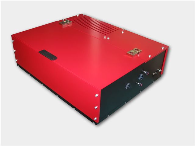
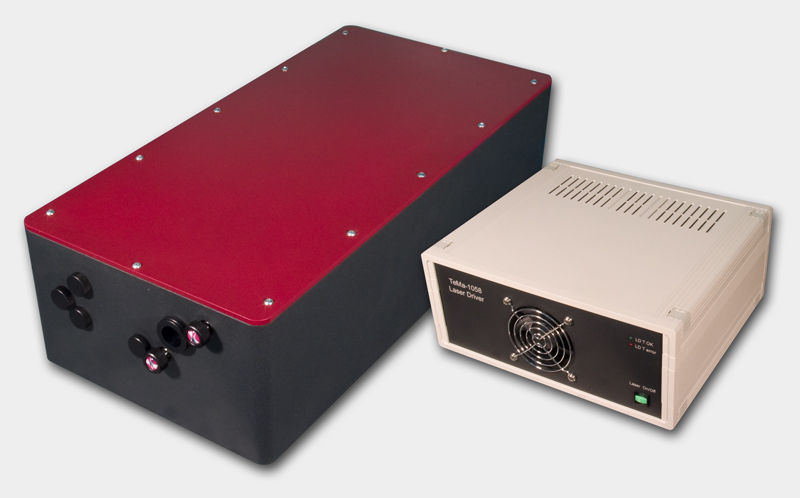
DPSS DMPLH lasers
DPSS DMP LH series lasers will pump your Ti:Sapphire laser.
There are LH series lasers installed all over the world pumping all makes & models
of oscillator. Anywhere from CEP-stabilized femtosecond Ti:Sapphire oscillators
to ultra-narrow-linewidth CW Ti:Sapphire oscillators. With up to 10 Watts CW
average power at 532nm in a TEMoo spatial mode, LH series
lasers has quickly proven itself
as the perfect DPSS pump laser for all types of Ti:Sapphire or dye laser.
Ideal for pumping of:
Trestles LH
Ti:Sapphire laser
T&D-scan laser
spectrometer based on narrow line CW Ti:Sapphire laser
|
 |
Pismo pulse picker
The Pismo pulse picker systems is as a pulse gating system that lets single
pulses or group of subsequent pulses from a femtosecond or picosecond pulse
train pass through the system, and stops other radiation. The system is
perfectly suitable for most commercial femtosecond oscillators and
amplifiers.
The system can pick either single pulses, shoot bursts (patterns of single
pulses) or pick group of subsequent pulses (wider square-shaped HV pulse
modification). HV pulse duration (i.e. gate open time) is 10 ns in the default
Pismo 8/1 model, but can be customized from 3 to 1250 ns upon request or made
variable. The frequency of the picked pulses starts with single shot to 1 kHz
for the basic model, and goes up to 100 kHz for the most advanced one.
The Pockels cell is supplied with a control unit that is capable of synching
to the optical pulse train via a built-in photodetector unit, while electric
trigger signal is also accepted. Two additional delay channels are available
for synching of other equipment to the pulse picker operation. Moreover, USB
connectivity and LabView-compatible drivers save a great deal of your time
on storing and recalling presets, and setting up some automated experimental
setups. One control unit is capable of driving of up to 3 Pockels cells, and
this comes handy in complex setups or contrast-improving schemes. The system
can also be modified to supply two HV pulses to one Pockels cell unit,
making it a 2-channel pulse picker system. This may be essential for
injection/ejection purposes when building a regenerative or multipass
amplifier system.
|
 |
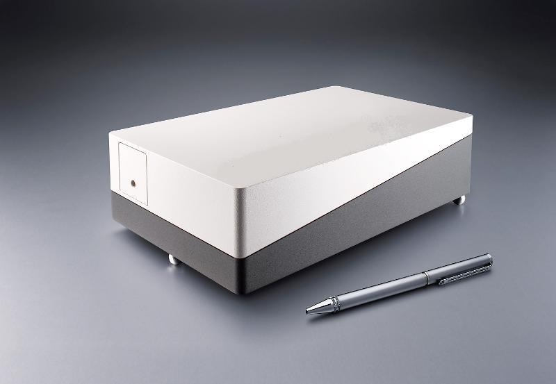
Tourmaline Yb-SS-1058/100 Femtosecond solid state laser system
The Yb-doped Tourmaline Yb-SS laser radiates at 1058±2 nm
with more than 1 W of average power, and enables the user to enjoy
Ti:Sapphire level power at over-micron wavelengths. This new design from Del
Mar's engineers features an integrated pump diode module for greater system
stability and turn-key operation. The solid bulk body of the laser ensures
maximum rigidity, while self-starting design provides for easy
"plug-and-play" operation.
|
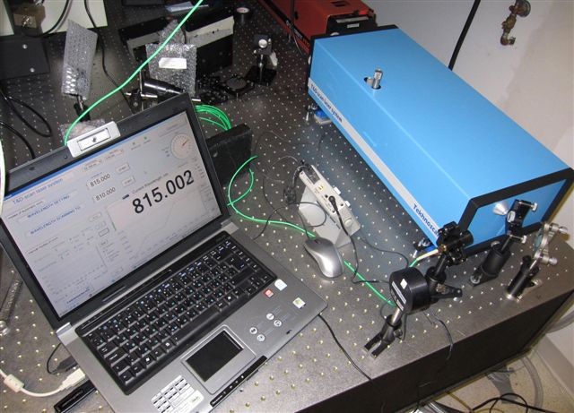 |
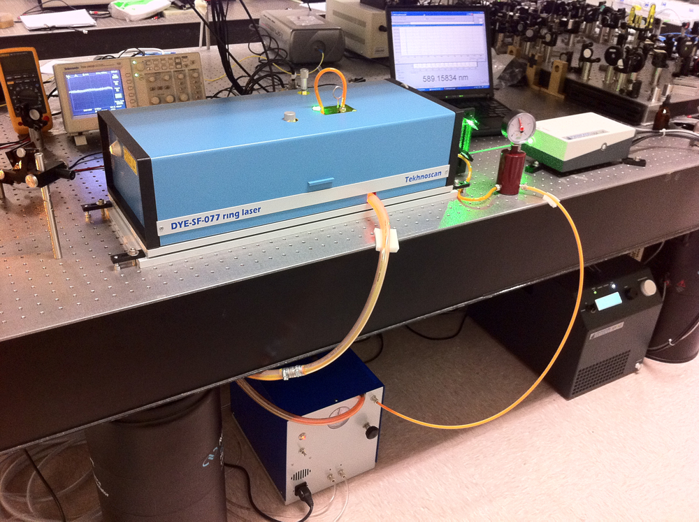
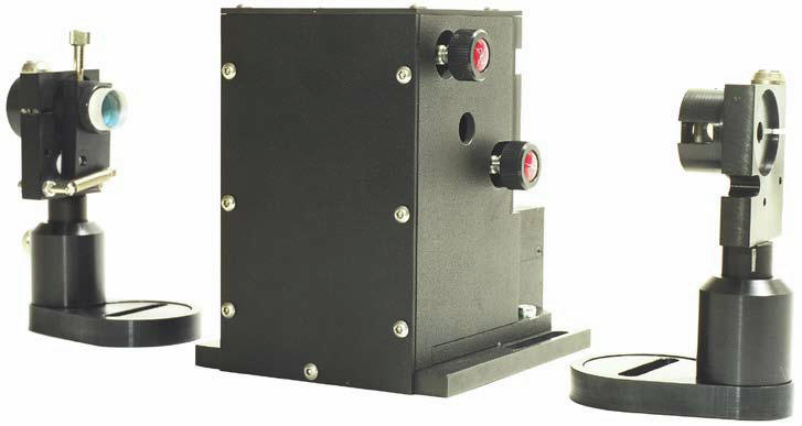
New laser spectrometer
T&D-scan for research that
demands high resolution and high spectral
density in UV-VIS-NIR spectral domains - now available with
new pump option!
The
T&D-scan
includes
a CW ultra-wide-tunable narrow-line laser, high-precision wavelength meter,
an electronic control unit driven through USB interface as well as a
software package. Novel advanced design of the fundamental laser component
implements efficient intra-cavity frequency doubling as well as provides a
state-of-the-art combined ultra-wide-tunable Ti:Sapphire & Dye laser
capable of covering together a
super-broad spectral range between 275 and 1100 nm. Wavelength
selection components as well as the position of the non-linear crystal are
precisely tuned by a closed-loop control
system, which incorporates highly accurate wavelength meter.Reserve a
spot in our CW lasers training
workshop in San Diego, California. Come to
learn how to build a
CW
Ti:Sapphire laser from a kit
|
|
Femtosecond fiber laser Model Pearl-70P300
-
request a quote
Femtosecond pulsed lasers are used in many fields of physics, biology,
medicine and many other natural sciences and applications: material processing,
multiphoton microscopy, «pump-probe» spectroscopy, parametric generation and
optical frequency metrology. Femtosecond fiber lasers offer stable and steady
operation without constant realignment.
The Pearl-70P300 laser comprises: a passively mode-locked fiber laser, providing
pulses with repetition rate 60 MHz and having duration of 250-5000 fs, an
amplifier based on Er3+ doped fiber waveguide with pumping by two laser diodes,
a prism compressor for amplified pulse compression. |
 |
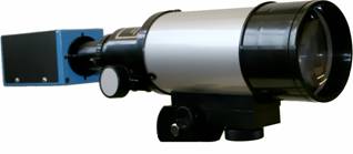
Near IR viewers
High performance infrared
monocular viewers are designed to observe radiation emitted by
infrared sources. They can be used to observe indirect radiation of IR
LED's and diode lasers, Nd:YAG, Ti:Sapphire, Cr:Forsterite, dye lasers and
other laser sources. IR viewers are ideal for applications involving the
alignment of infrared laser beams and of optical components in
near-infrared systems. Near IR viewers
sensitive to laser radiation up to 2000 nm.
The light weight, compact monocular may be used as a hand-held or facemask
mounted for hands free operation.
Ultraviolet viewers are
designed to observe radiation emitted by UV sources. |
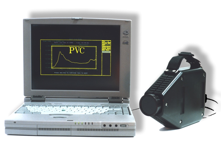 |
AOTF Infrared Spectrometer
Del Mar Photonics offer a handheld
infrared spectrometer based on the
acousto-optic tunable filter (AOTF). This instrument is about the size and
weight of a video camera, and can be battery operated. This unique, patented
device is all solid-state with no moving parts. It has been sold for a wide
variety of applications such as liquid fuel analysis, pharmaceutical analysis,
gas monitoring and
plastic analysis.
Miniature AOTF infrared spectrometer uses
a crystal of tellurium dioxide to scan the wavelength. Light from a light source enters
the crystal, and is diffracted into specific wavelengths. These wavelengths are
determined by the frequency of the electrical input to the crystal. Since there
are no moving parts, the wavelength scanning can be extremely fast. In addition,
specific wavelengths can be chosen by software according to the required algorithm, and therefore can be modified without changing the
hardware. After the infrared radiation reflects off of the sample, it is
converted into an electrical signal by the detector and analyzed by the
computer. Del Mar Photonics is looking for international distributors for
RAVEN - AOTF IR spectrometer for plastic identification and for variety of
scientific and industrial collaborations to explore futher commercial potential
of AOTF technology.
New:
AOTF spectrometer to measure lactose, fat and proteins in milk
|
 |
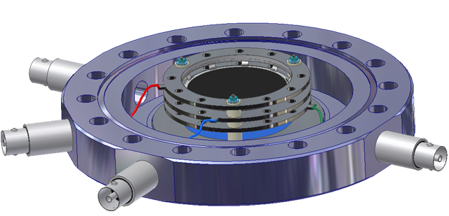
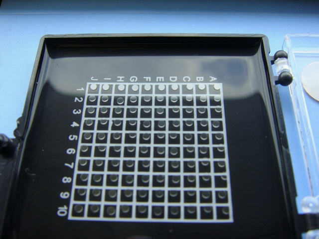
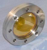
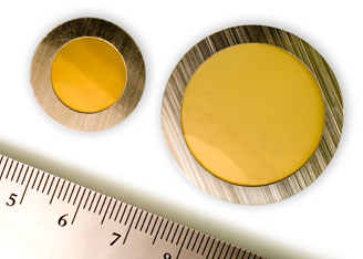
Open Microchannel Plate Detector
MCP-MA25/2 -
now in stock!
Microchannel Plate Detectors MCP-MA series are an open MCP detectors
with one or more microchannel plates and a single metal anode. They are intended
for time-resolved detection and make use of high-speed response properties of
the MCPs. MCP-MA detectors are designed for photons and particles detection in
vacuum chambers or in the space.
MCP-MA detectors are used in a variety of applications including UV, VUV and EUV
spectroscopy, atomic and molecular physics, TOF mass–spectrometry of clusters
and biomolecules, surface studies and space research.
MCP-MA detectors supplied as a totally assembled unit that can be easily mounted
on any support substrate or directly on a vacuum flange. They also can be
supplied premounted on a standard ConFlat flanges.
buy online -
ask for research discount!
|
 |
Hummingbird EMCCD camera
The digital Hummingbird
EMCCD camera combines high sensitivity, speed and high resolution.
It uses Texas Instruments' 1MegaPixel Frame Transfer Impactron device which
provides QE up to 65%.
Hummingbird comes with a standard CameraLink output.
It is the smallest and most rugged 1MP EMCCD camera in the world.
It is ideally suited for any low imaging application such as hyperspectral
imaging, X-ray imaging, Astronomy and low light surveillance.
It is small, lightweight, low power and is therefore the ideal camera for
OEM and integrators.
buy online |
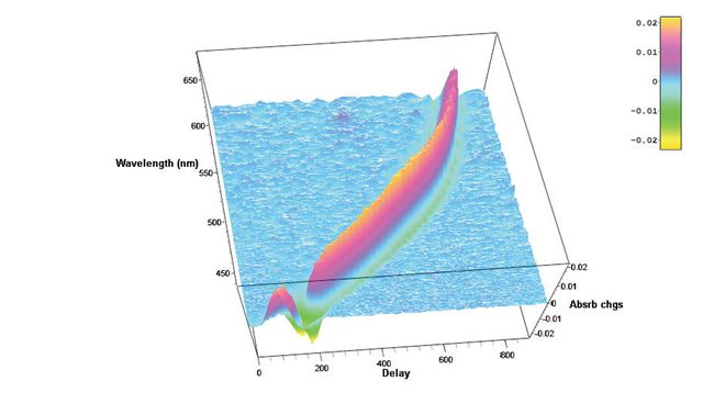 |
Hatteras-D
femtosecond transient absorption data acquisition system
Future nanostructures and biological nanosystems will take
advantage not only of the small dimensions of the objects but of the
specific way of interaction between nano-objects. The interactions
of building blocks within these nanosystems will be studied and optimized on
the
femtosecond time scale - says Sergey Egorov, President and CEO of Del Mar
Photonics, Inc. Thus we put a lot of our efforts and resources into the
development of new Ultrafast
Dynamics Tools such as our Femtosecond Transient Absorption Measurements
system Hatteras. Whether you want to
create a new photovoltaic system that will efficiently convert photon energy
in charge separation, or build a molecular complex that will dump photon energy
into local heat to kill cancer cells, or create a new fluorescent probe for
FRET microscopy, understanding of internal dynamics on femtosecond time scale
is utterly important and requires advanced measurement techniques.Reserve a
spot in our Ultrafast Dynamics Tools
training workshop in San Diego, California.
|
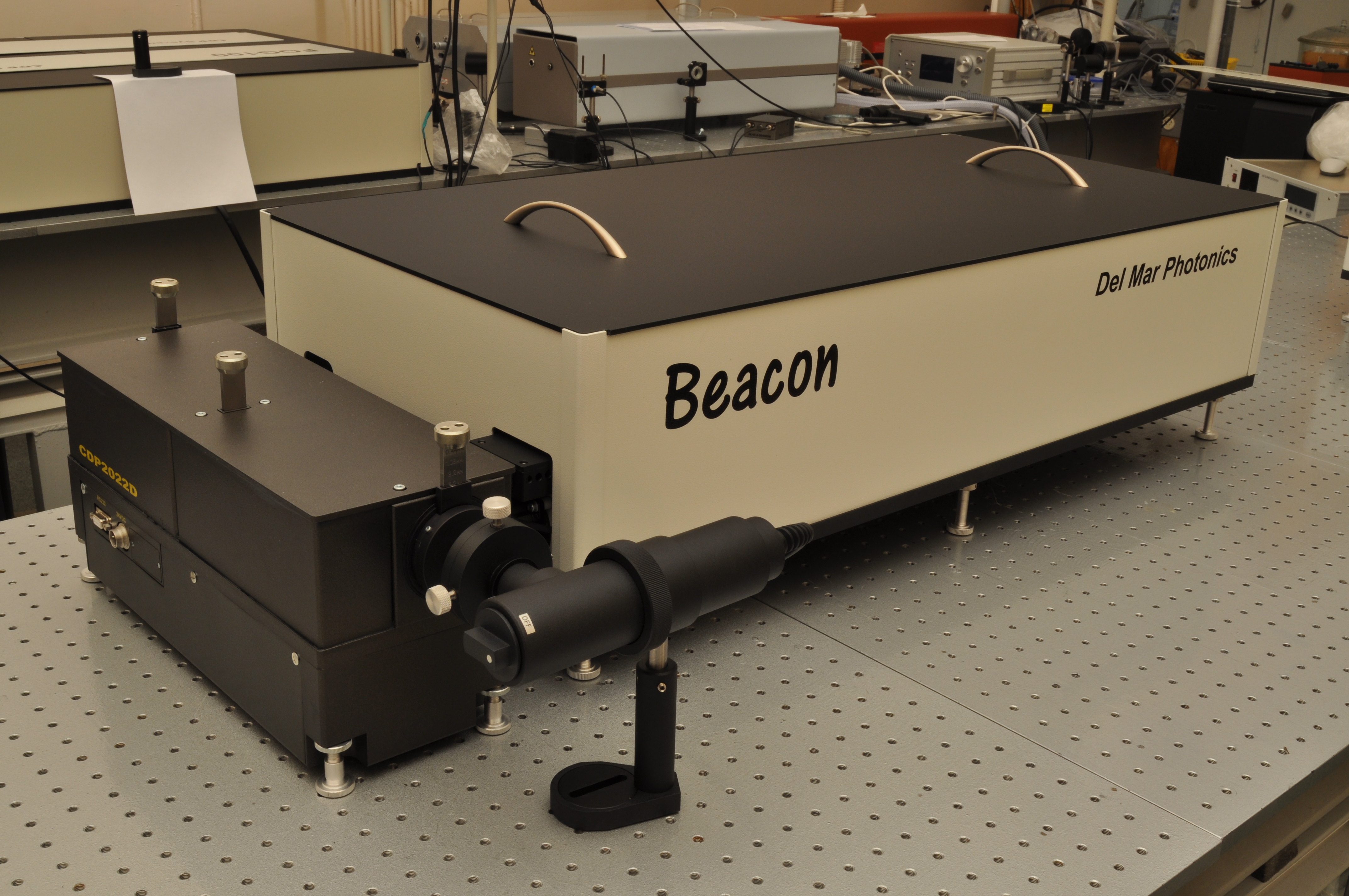 |
Beacon Femtosecond Optically Gated Fluorescence Kinetic Measurement System
-
request a quote -
pdf
Beacon together with Trestles Ti:sapphire oscillator, second and third harmonic
generators. Femtosecond optical gating (FOG) method gives best temporal
resolution in light-induced fluorescence lifetime measurements. The resolution
is determined by a temporal width of femtosecond optical gate pulse and doesn't
depend on the detector response function. Sum frequency generation (also called
upconversion) in nonlinear optical crystal is used as a gating method in the
Beacon femtosecond fluorescence kinetic measurement system. We offer
Beacon-DX for operation together with Ti: sapphire femtosecond oscillators
and Beacon-DA for operation together with femtosecond amplified pulses.
Reserve a
spot in our Ultrafast Dynamics Tools
training workshop in San Diego, California.
|
 |
Wavefront Sensors: ShaH Family
A family of ShaH wavefront sensors represents recent progress of Del Mar
Photonics in Shack-Hartmann-based technology. The performance of Shack-Hartmann
sensors greatly depends on the quality of the lenslet arrays used. Del Mar
Photonics. developed a proprietary process of lenslet manufacturing, ensuring
excellent quality of refractive lenslet arrays. The arrays can be AR coated on
both sides without interfering with the micro-lens surface accuracy. Another
advantage of the ShaH wavefront sensors is a highly optimized processing code.
This makes possible real-time processing of the sensor data at the rate
exceeding 1000 frames per second with a common PC. Due to utilizing low-level
programming of the video GPU, it is possible to output the wavefront data with a
resolution up to 512x512 pixels at a 500+ Hz frame rate. This mode is favorable
for controlling modern LCOS wavefront correctors.
The family of ShaH wavefront sensors includes several prototype models, starting
from low-cost ShaH-0620 suitable for teaching laboratory to a high-end
high-speed model, ShaH-03500. The latter utilizes a back-illuminated EM-gain CCD
sensor with cooling down to -100°C. This makes it possible to apply such a
wavefront sensor in astronomy, remote sensing, etc.
|
 |
Terahertz systems, set ups and components
New band pass and long pass THz optical filters based on porous silicon and metal mesh technologies.
Band pass filters with center wavelengths from 30 THz into GHz range and transmissions up to 80% or better. Standard designs
with clear aperture diameters from 12.5 to 37.5 mm.
Long pass filters with standard rejection edge wavelengths from 60 THz into GHz range. Maximum transmission up to 80% or
better, standard designs at 19.0 and 25.4 mm diameters.
Excellent thermal (from cryogenic to 600 K) and mechanical properties
THz products:
Portable Terahertz Source
THz Spectrometer kit with Antenna
THz transmission setup
THz time domain spectrometer Pacifica fs1060pca
THz time domain spectrometer Pacifica fs780pca
THz detectors: Golay cell and LiTaO3 piroelectric detectors
PCA - Photoconductive Antenna as THz photomixer
Pacifica THz Time Domain Spectrometer - Trestles Pacifica
Holographic Fourier Transform Spectrometer for THz Region
Wedge TiSapphire Multipass Amplifier System - THz pulses generation
Terahertz Spectroscopic Radar Mobile System for Detection of Concealed Explosives
Band pass filters with center wavelengths from 30 THz into GHz range
Long pass filters with standard rejection edge wavelengths from 60 THz into GHz range
Generation of THz radiation using lithium niobate
Terahertz crystals (THz): ZnTe, GaAs, GaP, LiNbO3 - Wedge ZnTe
Silicon Viewports for THz radiation
Aspheric collimating silicon lens - Aspheric focusing silicon lens
|
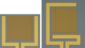 |
iPCA - interdigital Photoconductive Antenna for terahertz waves
Large area broadband antenna with lens array and high emitter conversion
efficiency
iPCA with LT-GaAs absorber, microlens array for laser excitation wavelengths
l £ 850
nm, adjusted hyperhemispherical silicon lens with a high power conversion
efficiency of 0.2 mW THz power / W optical power. The iPCA can be used also
as large area THz detector. The two types iPCAp and iPCAs have the same
active interdigital antenna area but different contact pad directions with
respect to the electrical THz field.
Interdigital Photoconductive Antenna for terahertz waves generation using
femtosecond Ti:Sapphire laser
THz books |
|
|
Fifth Harmonic Generator for
Nd:YAG lasers
The Fifth Harmonic Generator model LG105 is compatible with any pulsed
Nd:YAG laser, and is designed to produce UV-radiation at 213 nm. The
Nd:YAG laser, equipped with LG105, is a versatile device, and in many
applications can eliminate the necessity for excimer lasers. Solid state
technology that does not use toxic gases and costs less gives you the
advantages of both consistent, day-to-day operation and low maintenance. A
high quality BBO crystal is used in the LG105 as the non-linear element,
providing up to 20% conversion efficiency into 213 nm. The non-linear
crystal is placed in a special cell ensuring long lifetime of BBO without
any degradation or breakage. A harmonic separation system installed in LG105
provides nearly 100 % spectral purity of the output at 213 nm. The LG105
Fifth Harmonic Generator gives you not only high power output but also
excellent radiation stability
|
 |
IntraStage lowers the cost
of test data management!
Struggling with gigabytes or terabytes of test data?
IntraStage easily transforms test
data from disparate sources into web-based quality metrics and engineering
intelligence you can use.
Contact
us today to discuss your test management requirements and specifications of your
application.
|